PS/2 Mouse/Keyboard Protocol
This article is Copyright 1999, Adam Chapweske
Introduction:
The PS/2 device interface, used by many modern mice and keyboards, was developed by IBM and originally appeared in the IBM Technical Reference Manual. However, this document has not been printed for many years and as far as I know, there is currently no official publication of this information. I have not had access to the IBM Technical Reference Manual, so all information on this page comes from my own experiences as well as help from the references listed at the bottom of this page.
This document descibes the interface used by the PS/2 mouse, PS/2 keyboard, and AT keyboard. I'll cover the physical and electrical interface, as well as the protocol. If you need higher-level information, such as commands, data packet formats, or other information specific to the keyboard or mouse, I have written separate documents for the two devices:
The PS/2 (AT) Keyboard InterfaceI also encourage you to check this site's main page for more information related to this topic, including projects, code, and links related to the mouse and keyboard. Please send an email if you find any mistakes or bad advice on this site.
The PS/2 Mouse Interface
The Physical Interface:
The physical PS/2 port is one of two styles of connectors: The 5-pin DIN or the 6-pin mini-DIN. Both connectors are completely (electrically) similar; the only practical difference between the two is the arrangement of pins. This means the two types of connectors can easily be changed with simple hard-wired adaptors. These cost about $6 each or you can make your own by matching the pins on any two connectors. The DIN standard was created by the German Standardization Organization (Deutsches Institut fuer Norm) . Their website is at http://www.din.de (this site is in German, but most of their pages are also available in English.)
PC keyboards use either a 6-pin mini-DIN or a 5-pin DIN connector. If your keyboard has a 6-pin mini-DIN and your computer has a 5-pin DIN (or visa versa), the two can be made compatible with the adaptors described above. Keyboards with the 6-pin mini-DIN are often referred to as "PS/2" keyboards, while those with the 5-pin DIN are called "AT" devices ("XT" keyboards also used the 5-pin DIN, but they are quite old and haven't been made for many years.) All modern keyboards built for the PC are either PS/2, AT, or USB. This document does not apply to USB devices, which use a completely different interface.
Mice come in a number of shapes and sizes (and interfaces.)
The most popular type is probably the PS/2 mouse, with USB mice gaining
popularity. Just a few years ago, serial mice were also quite popular,
but the computer industry is abandoning them in support of USB and PS/2 devices.
This document applies only to PS/2 mice. If you want to interface
a serial or USB mouse, there's plenty of information available elsewhere
on the web.
The cable connecting the keyboard/mouse to the computer is usually about
six feet long and consists of four to six 26 AWG wires surrounded by a thin
layer of mylar foil sheilding. If you need a longer cable, you can
buy PS/2 extenstion cables from most consumer electronics stores. You
should not connect multiple extension cables together. If you need a
30-foot keyboard cable, buy a 30-foot keyboard cable. Do not simply
connect five 6-foot cables together. Doing so could result in poor communication
between the keyboard/mouse and the host.
As a side note, there is one other type of connector you may run into on keyboards. While most keyboard cables are hard-wired to the keyboard, there are some whose cable is not permanently attached and come as a separate component. These cables have a DIN connector on one end (the end that connects to the computer) and a SDL (Sheilded Data Link) connector on the keyboard end. SDL was created by a company called "AMP." This connector is somewhat similar to a telephone connector in that it has wires and springs rather than pins, and a clip holds it in place. If you need more information on this connector, you might be able to find it on AMP's website at http://www.connect.amp.com. I have only seen this type of connector on (old) XT keyboards, although there may be AT keyboards that also use the SDL. Don't confuse the SDL connector with the USB connector--they probably both look similar in my diagram below, but they are actually very different. Keep in mind that the SDL connector has springs and moving parts, while the USB connector does not.
The pinouts for each connector are shown below:

(Plug) |

(Socket) |
5-pin DIN (AT/XT): 1 - Clock 2 - Data 3 - Not Implemented 4 - Ground 5 - Vcc (+5V) |

(Plug) |

(Socket) |
6-pin Mini-DIN (PS/2): 1 - Data 2 - Not Implemented 3 - Ground 4 - Vcc (+5V) 5 - Clock 6 - Not Implemented |
|
|
|
6-pin SDL: A - Not Implemented B - Data C - Ground D - Clock E - Vcc (+5V) F - Not Implemented |
The Electrical Interface:
Note: Throughout this document, I will use the more general term "host" to refer to the computer--or whatever the keyboard/mouse is connected to-- and the term "device" will refer to the keyboard/mouse.
Vcc/Ground provide power to the keyboard/mouse. The keyboard
or mouse should not draw more than 100 mA from the host and care must be
taken to avoid transient surges. Such surges can be caused by "hot-plugging"
a keyboard/mouse (ie, connect/disconnect the device while the computer's
power is on.) Older motherboards had a surface-mounted fuse protecting
the keyboard and mouse ports. When this fuse blew, the motherboard was
useless to the consumer, and non-fixable to the average technician. Most
newer motherboards use auto-reset "Poly" fuses that go a long way to remedy
this problem. However, this is not a standard and there's still plenty
of older motherboards in use. Therefore, I recommend against hot-plugging
a PS/2 mouse or keyboard.
Summary: Power Specifications
Vcc = +5V.
Max Current = 100 mA.
The Data and Clock lines are both open-collector with pullup resistors
to +5V. An "open-collector" interface has two possible state: low,
or high impedance. In the "low" state, a transistor pulls the line to
ground level. In the "high impedance" state, the interface acts as
an open circuit and doesn't drive the line low or high. Furthermore, a "pullup"
resistor is connected between the bus and Vcc so the bus is pulled high if
none of the devices on the bus are actively pulling it low. The exact
value of this resistor isn't too important (1~10 kOhms); larger resistances
result in less power consumption and smaller resistances result in a faster
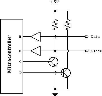
rise time. A general open-collector interface is shown below:
Figure 1: General open-collector interface. Data and Clock are read on the microcontroller's pins A and B, respectively. Both lines are normally held at +5V, but can be pulled to ground by asserting logic "1" on C and D. As a result, Data equals D, inverted, and Clock equals C, inverted.
Note: When looking through examples on this website, you'll notice I use
a few tricks when implementing an open-collector interface with PIC microcontrollers.
I use the same pin for both input and output, and I enable the PIC's
internal pullup resistors rather than using external resistors. A line
is pulled to ground by setting the corresponding pin to output, and writing
a "zero" to that port. The line is set to the "high impedance" state
by setting the pin to input. Taking into account the PIC's built-in
protection diodes and sufficient current sinking, I think this is a valid
configuration. Let me know if your experiences have proved otherwise.
Communication: General Description
The PS/2 mouse and keyboard implement a bidirectional synchronous
serial protocol. The bus is "idle" when both lines are high (open-collector).
This is the only state where the keyboard/mouse is allowed begin transmitting
data. The host has ultimate control over the bus and may inhibit
communication at any time by pulling the Clock line low.
The device always generates the clock signal. If the host
wants to send data, it must first inhibit communication from the device by
pulling Clock low. The host then pulls Data low and releases Clock.
This is the "Request-to-Send" state and signals the device to start
generating clock pulses.
All data is transmitted one byte at a time and each byte is sent in a frame consisting of 11-12 bits. These bits are:Summary: Bus States
Data = high, Clock = high: Idle state.
Data = high, Clock = low: Communication Inhibited.
Data = low, Clock = high: Host Request-to-Send
- 1 start bit. This is always 0.
- 8 data bits, least significant bit first.
- 1 parity bit (odd parity).
- 1 stop bit. This is always 1.
- 1 acknowledge bit (host-to-device communication only)
The parity bit is set if there is an even number of 1's in the data
bits and reset (0) if there is an odd number of 1's in the data bits.
The number of 1's in the data bits plus the parity bit always add up to
an odd number (odd parity.) This is used for error detection. The
keyboard/mouse must check this bit and if incorrect it should respond as
if it had received an invalid command.
Data sent from the device to the host is read on the falling edge of the clock signal; data sent from the host to the device is read on the rising edge. The clock frequency must be in the range 10 - 16.7 kHz. This means clock must be high for 30 - 50 microseconds and low for 30 - 50 microseconds.. If you're designing a keyboard, mouse, or host emulator, you should modify/sample the Data line in the middle of each cell. I.e. 15 - 25 microseconds after the appropriate clock transition. Again, the keyboard/mouse always generates the clock signal, but the host always has ultimate control over communication.
Timing is absolutely crucial. Every time quantity I give in this article must be followed exactly.
Communication: Device-to-Host
The Data and Clock lines are both open collector. A resistor is connected between each line and +5V, so the idle state of the bus is high. When the keyboard or mouse wants to send information, it first checks the Clock line to make sure it's at a high logic level. If it's not, the host is inhibiting communication and the device must buffer any to-be-sent data until the host releases Clock. The Clock line must be continuously high for at least 50 microseconds before the device can begin to transmit its data.
As I mentioned in the previous section, the keyboard and mouse use a serial protocol with 11-bit frames. These bits are:
- 1 start bit. This is always 0.
- 8 data bits, least significant bit first.
- 1 parity bit (odd parity).
- 1 stop bit. This is always 1.
Figure 2: Device-to-host communication.
The Data line changes state when Clock is high and that data is valid
when Clock is low.
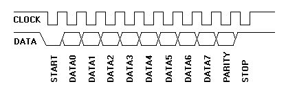
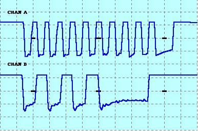
Figure 3: Scan code for the "Q" key (15h) being sent from a keyboard to the computer. Channel A is the Clock signal; channel B is the Data signal.
---
The clock frequency is 10-16.7 kHz. The time from the rising
edge of a clock pulse to a Data transition must be at least 5 microseconds.
The time from a data transition to the falling edge of a clock pulse must
be at least 5 microseconds and no greater than 25 microseconds.
The host may inhibit communication at any time by pulling the Clock
line low for at least 100 microseconds. If a transmission is inhibited
before the 11th clock pulse, the device must abort the current transmission
and prepare to retransmit the current "chunk" of data when host releases
Clock. A "chunk" of data could be a make code, break code, device ID,
mouse movement packet, etc. For example, if a keyboard is interrupted
while sending the second byte of a two-byte break code, it will need to retransmit
both bytes of that break code, not just the one that was interrupted.
If the host pulls clock low before the first high-to-low clock transition, or after the falling edge of the last clock pulse, the keyboard/mouse does not need to retransmit any data. However, if new data is created that needs to be transmitted, it will have to be buffered until the host releases Clock. Keyboards have a 16-byte buffer for this purpose. If more than 16 bytes worth of keystrokes occur, further keystrokes will be ignored until there's room in the buffer. Mice only store the most current movement packet for transmission.
Host-to-Device Communication:
The packet is sent a little differently in host-to-device communication...
First of all, the PS/2 device always generates the clock signal. If the host wants to send data, it must first put the Clock and Data lines in a "Request-to-send" state as follows:
- Inhibit communication by pulling Clock low for at least 100 microseconds.
- Apply "Request-to-send" by pulling Data low, then release Clock.
After the stop bit is received, the device will acknowledge the received byte by bringing the Data line low and generating one last clock pulse. If the host does not release the Data line after the 11th clock pulse, the device will continue to generate clock pulses until the the Data line is released (the device will then generate an error.)
The host may abort transmission at time before the 11th clock pulse (acknowledge bit) by holding Clock low for at least 100 microseconds.
To make this process a little easier to understand, here's the steps the host must follow to send data to a PS/2 device:
1) Bring the Clock line low for at least 100 microseconds.
2) Bring the Data line low.
3) Release the Clock line.
4) Wait for the device to bring the Clock line low.
5) Set/reset the Data line to send the first data bit
6) Wait for the device to bring Clock high.
7) Wait for the device to bring Clock low.
8) Repeat steps 5-7 for the other seven data bits and the parity bit
9) Release the Data line.
10) Wait for the device to bring Data low.
11) Wait for the device to bring Clock low.
12) Wait for the device to release Data and Clock
Figure 3 shows this graphically and Figure
4 separates the timing to show which signals are generated by the host,
and which are generated by the PS/2 device. Notice the change in timing
for the "ack" bit--the data transition occours when the Clock line is
high (rather than when it is low as is the case for the other 11 bits.)
Figure 3: Host-to-Device Communication.
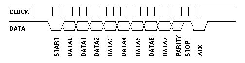
Figure 4: Detailed host-to-device communication.
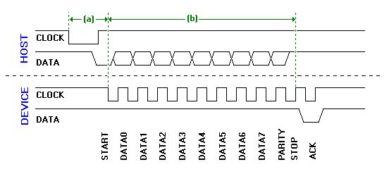
Referring to Figure 4, there's two time quantities the host looks for. (a) is the time it takes the device to begin generating clock pulses after the host initially takes the Clock line low, which must be no greater than 15 ms. (b) is the time it takes for the packet to be sent, which must be no greater than 2ms. If either of these time limits is not met, the host should generate an error. Immediately after the "ack" is received, the host may bring the Clock line low to inhibit communication while it processes data. If the command sent by the host requires a response, that response must be received no later than 20 ms after the host releases the Clock line. If this does not happen, the host generates an error.
Other Sources / References: