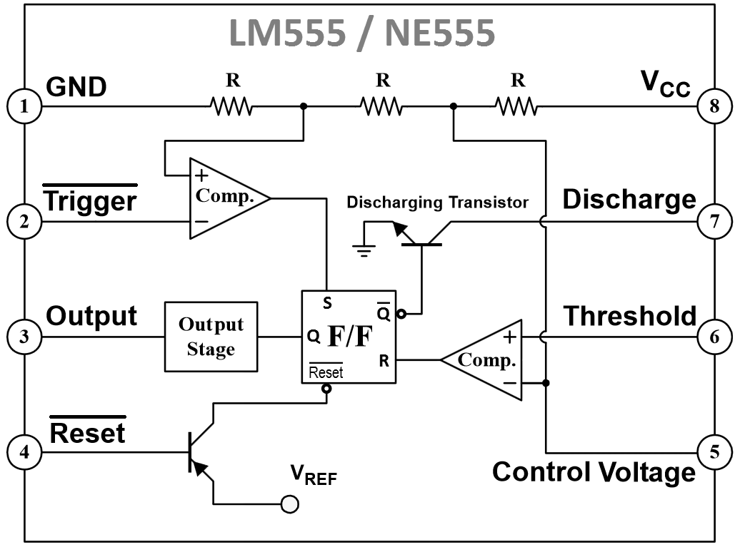
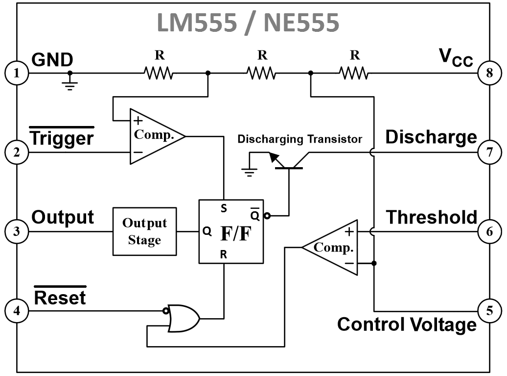
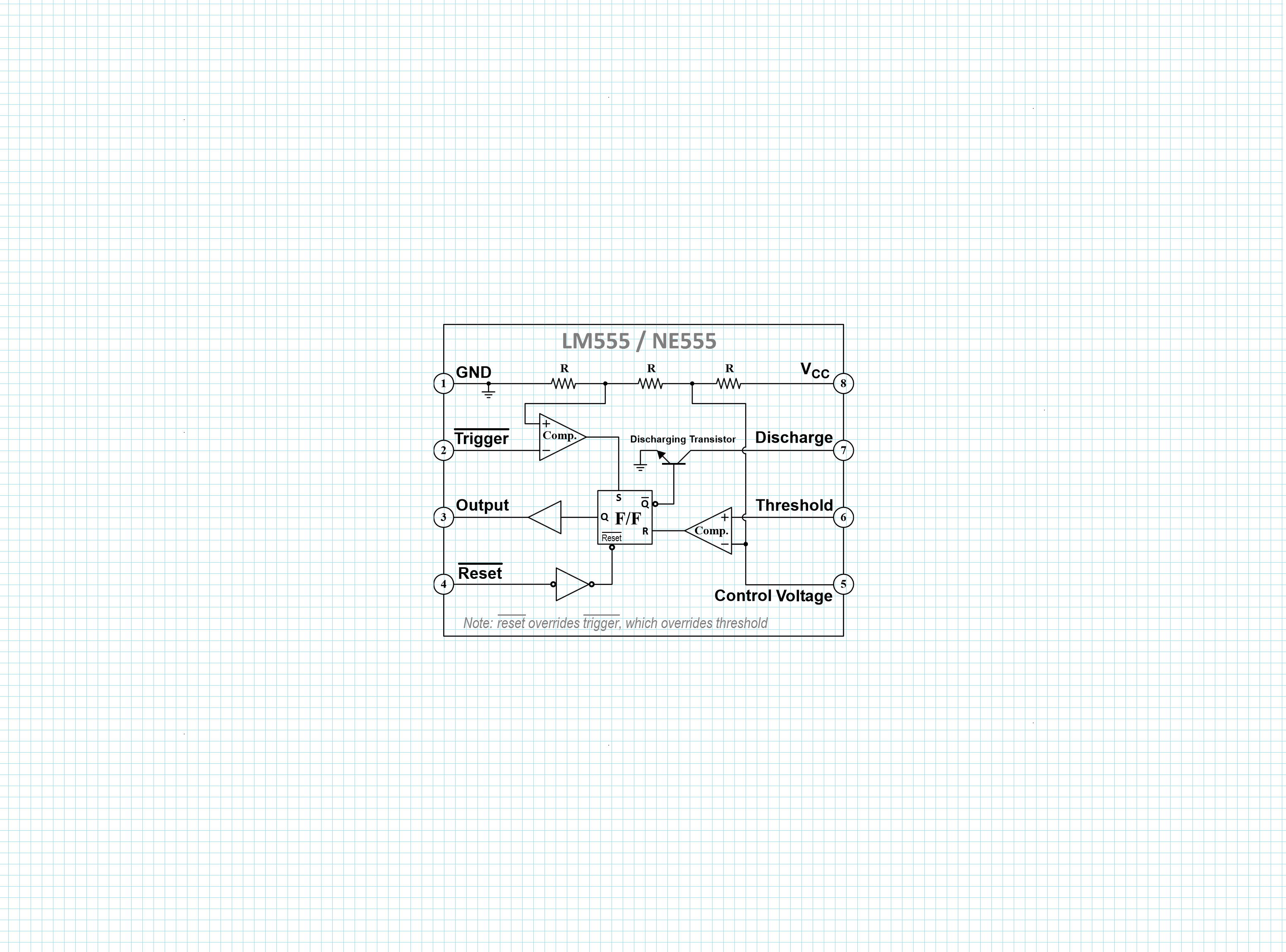
LM555/NE555 timer

Click on image for larger version (or alt #1, or alt #2, or alt #3)
| ¬Trigger | ¬Reset | Threshold | Output | ||
|---|---|---|---|---|---|
| 555 pin | 2 | 4 | 6 | 3 | |
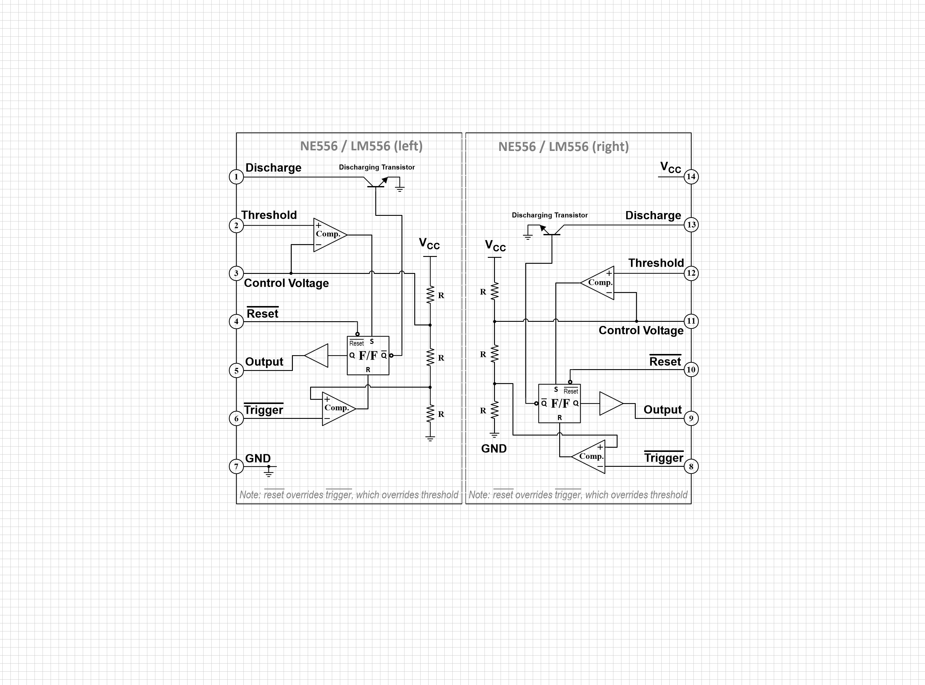
| 556 pin (L) | 6 | 4 | 2 | 5 | |
| 556 pin (R) | 8 | 10 | 12 | 9 | |
| 0* | 0* | 0 | 0 | ¬reset overrides ¬trigger | |
| 0* | 0* | 1* | 0 | ¬reset overrides ¬trigger | |
| 0* | 1 | 0 | 1 | = ¬trigger | |
| 0* | 1 | 1* | 1 | ¬trigger overrides threshold | |
| 1 | 0* | 0 | 0 | = ¬reset | |
| 1 | 0* | 1* | 0 | = ¬reset | |
| 1 | 1 | 0 | ? | current flip-flop state | |
| 1 | 1 | 1* | 0 | = threshold |
¬trigger sets the flip-flop.
threshold or ¬reset resets the flip-flop.
¬reset overrides ¬trigger, which overrides threshold.
* = active state (¬trigger & ¬reset are active-low, threshold is active-high)
¬trigger is relative to 1/3 Vcc and threshold is relative to 2/3 Vcc, unless changed via pin 5 (control voltage)
TI NE556 (or LM556 with erroneous block diagram)
TI LMC555 CMOS low-power timer
TI TLC555 CMOS low-power timer
Intersil ICM7555 & ICM7556 CMOS low-power timers
CSS555 micropower programmable timer
555 & 556 timer application notes
Rob Paisley's 555 timer circuits
The seldom-used Control Voltage pin can occasionally be useful
")
")